
Pipe Bursting and Splitting
PIPE BURSTING / SPLITTING - TECHNIQUE
Pipe bursting and pipe splitting are trenchless methods used to replace existing pipelines with PE100 or PE100-RC in the same alignment without physically removing the existing pipeline. Bursting and splitting, by using the existing alignment to replace a pipe, avoids the need to secure any additional right-of-way to install the PE100 replacement pipe. Bursting and splitting can be used to upsize the pipeline thereby increasing its flow capacity if this is necessary.
Pipe bursting is used to replace brittle pipes such as clay, asbestos cement, concrete and cast iron by pulling through the host pipe a static or dynamic bursting head to fragment the existing pipe and an expander cone, sometimes incorporated in the bursting head, to push the fragments outwards into the surrounding ground. Simultaneously, a new PE100 pipe attached to the back of the bursting head is installed in the same alignment as the original pipe.
Pipe splitting is used to replace ductile pipes such as steel, ductile iron and plastics through cutting them into segments along their length using an internal head with cutter blades. As with pipe bursting a new PE100 pipe attached to the back of the cutting head is installed in the same alignment as the original pipe.
There are three methods of pipe bursting: pneumatic, hydraulic, and static pull. The difference between them is in the source of energy and the method of breaking the old pipe. Pneumatic and hydraulic methods use dynamic force to break the old pipe whereas static pull uses a constant pull force. The selection of a specific method depends on soil conditions, groundwater conditions, degree of upsizing required, type of new pipe, construction of the existing pipeline, depth of the pipeline and availability of experienced contractors with suitable equipment. Static pipe bursting has replaced pneumatic bursting as the most commonly used variant primarily because of the absence of shock waves generated by a dynamic burster, which can cause damage to adjacent buried utilities.
Pipe splitting is necessarily a static pull method.
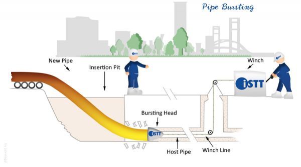
Image courtesy: INTERNATIONAL SOCIETY FOR TRENCHLESS TECHNOLOGY
Image courtesy Tracto-Technik GmbH & Co KG
The pipe bursting process consists of advancing a conical-shaped bursting head that has a diameter 50 to 100 mm larger than the new replacement pipe through the existing pipe. The radial expansion caused by the geometry of the bursting head surmounts the host pipe’s tensile and shear strength capacities, resulting in the fragmentation or splitting of the pipe. As the bursting head is pulled through the host pipe, the fragments are pushed into the resulting annulus, creating a cavity for the PE100 pipe which immediately follows the bursting head as it is simultaneously pulled or pushed into the newly formed cavity.
Pipe splitting uses the same principles as pipe bursting to replace pipes that are not brittle and therefore require cutting such as steel, ductile iron and plastic pipe. A typical pipe splitting head uses cutters or blades to slice the host pipe while an expansion shell head follows it and peels open the host pipe providing space for the new PE100 pipe.
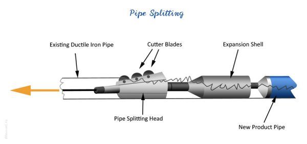
Image courtesy: INTERNATIONAL SOCIETY FOR TRENCHLESSTECHNOLOGY
PIPE BURSTING / SPLITTING - PE100 APPLICATIONS
- Water mains.
- Gas mains.
- Sewer rising mains.
- Replacement
PIPE BURSTING / SPLITTING - INSTALLATION PROCEDURE
.png)
Image courtesy Tracto-Technik GmbH & Co KG
Steel rods or cables are inserted into the existing pipe from the pulling shaft. When the rods or cable reach the insertion shaft, the bursting head is connected to them and the new pipe is connected to the rear of the head. A hydraulic unit in the pulling shaft pulls the rods or cable. The bursting/splitting head and the new PE100 pipe are pulled with the rod or the cable, fracturing or cutting the existing pipe and pushing the debris to the surrounding soil. The process continues until the bursting/splitting head reaches the pulling shaft, where it is separated from the new pipe. If a cable or winch is used the pulling process continues with minimum interruption, but the force available for the operation is less. if a rod assembly is used the pulling process is interrupted as each rod is removed and the string reconnected, but the pulling force can be greater.
If the PE100 is being dispensed from a coil the leading end of the coil must first be pulled through a straightener/re-rounder. See Sliplining for more details of pulling processes.
The continuous display and recording of the pulling force on the PE pipe at the winch is important in order to ensure that it cannot be subjected to and damaged by excessive pulling forces. In some countries (Germany, Spain & UK) the tensile forces on the new pipe must be monitored throughout the pipe bursting/splitting process. Measurement of tensile force is not feasible with dynamic pipe bursting methods.
.png)
Image courtesy Tracto-Technik GmbH & Co KG
.png)
Image courtesy Tracto-Technik GmbH & Co KG
PIPE BURSTING / SPLITTING - EQUIPMENT
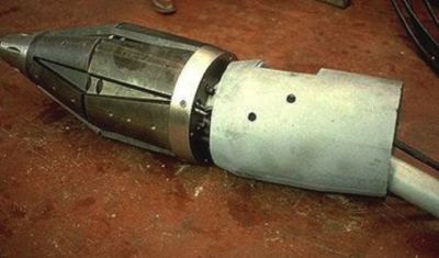
The main equipment used in pipe bursting and splitting is the burster/splitter head, an expander which may be incorporated into the burster/splitter head, pulling rods, a rod puller or winch and a hydraulic power pack. All dynamic and static burster heads incorporate cutting blades or cutting roller discs to concentrate the cutting forces Today's static heads have a leading end much smaller in diameter than the trailing (bursting) end, small enough to fit through the pipe that will be replaced. This guides the expander head through the existing pipe; it may also include "fins" that make first contact with the existing pipe. Using these fins as the primary breaking point is a very effective way to ensure that the pipe is broken along the entire circumference. All of the equipment used in a pipe bursting operation is powered by one or multiple hydraulic power generators.
For small diameters of brittle pipe material, such as cast iron or asbestos cement, the head is usually a simple blade and cone, such as these:
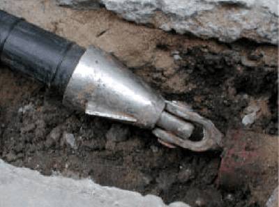
Image courtesy: Exova Utilities
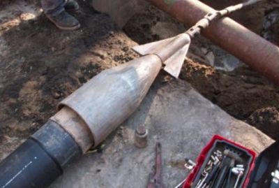
Image courtesy: Exova Utilities
.png)
.png)
Images courtesy Tracto-Technik GmbH & Co KG
For larger diameters the single blade is replaced by sets of rotary cutters. This ensures that the fragments are reasonably small whilst the bursting force is lower and the bursting action smoother.
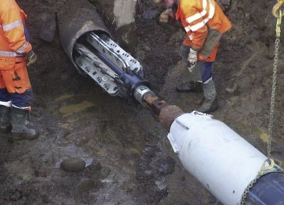
Image courtesy: Exova Utilities
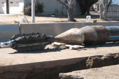
Image courtesy: Exova Utilities
For large diameter brittle pipes a hydraulically operated cutter head can be used in which the expanding leaves are extended outwards while the burster is static to provide the bursting action, after which they are retracted, the head pulled forward, and the process repeated:
Hydraulic pipe burster with expanding leaves retracted
Image courtsey : Exova Utilities
For pipe splitting a roller blade cutter is used which slits the pipe and opens it out. For larger diameters a special head that cuts the pipe into strips may be used, allowing larger replacement pipe to be installed:
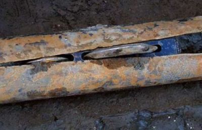
Image courtesy: Exova Utilities
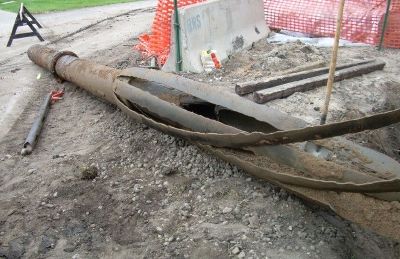
Image courtesy: Exova Utilities
.png)
Image courtesy Tracto-Technik GmbH & Co KG
.png)
Image courtesy Tracto-Technik GmbH & Co KG
At the entry end the equipment will be either a coil trailer and pipe straightener/re-rounder, or a set of rollers to carry the string, whilst at the exit end the equipment will be either a winch or a rod puller set within the trench. Winch or rod puller capacity depends on the diameter of the pipe to be burst/split. For the largest pipes this may be as high as 2500 kN. Note that this is the tensile load between winch and burster/splitter, and is not the tensile load on the PE100 pipe itself; this will be much lower.
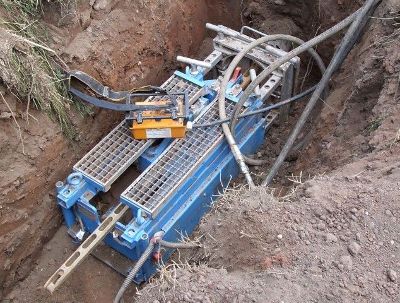
Image courtesy: Tracto-Technik GmbH & Co KG
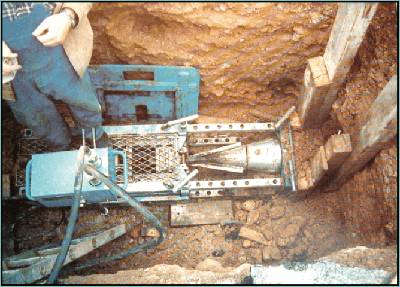
Image courtesy: Tracto-Technik GmbH & Co KG
These pictures show typical rod pullers in place, with the second showing the burster arriving at the end of the bursting operation.
PIPE BURSTING / SPLITTING - PRACTICALITIES
Pipe bursting and splitting are not without risk to adjacent buried infrastructure, particularly in the case of large diameters, large upsizes, and in infrastructure congested areas. Accurate location and identification of adjacent services is of paramount importance.
In addition all service connections on the line to be replaced must be disconnected prior to the works and reconnected afterwards to the new pipe. If there are frequent service connections, each with an excavation, alternative solutions may be more cost-effective while no more disruptive, though potentially more damaging to other buried infrastructure and the road structure itself. Service connections can be dealt with far more effectively using a core and vacuum technique and down the hole tooling.
It is also necessary to consider the risk of damage to the new PE pipe from the fragments of the old pipe. This is less of a concern in pipe splitting than in pipe bursting. If the fragments have not been well displaced by the burster or splitter cone they may scrape the PE100 pipe as it passes them. This risk is greater when the ground contains stones or cobbles which can cause the fragments to pile up rather than be pushed out of the way. Special coated PE100 pipes are available to reduce this risk
Soil Types and their effects
In order to ensure successful pipe bursting/splitting works it is essential to know the ground conditions. The method displaces fragments of the existing pipe into the soil and thus is most appropriate for compressible soils. Ground conditions suitable for pipe bursting/splitting include clays, silt, generally soft cohesive material. Loose and medium sands and gravels are also feasible.
Diameter, pressure and Length Range
For pressure pipes and services pipe bursting and pipe splitting can be used in diameters from 50mm to 800mm and over lengths of up to 200 metres in a single pull. These are the limits of the system and there is a trade-off between diameter and length with upsizing also an important factor in determining the practicality and length possible.
Pressure is a function of the SDR of the installed PE100 pipe
EXCAVATIONS
See also Excavations, pit sizes, Space and Access
DESIGN, SPECIFICATION & PLANNING
Design
- Fluid/hydraulic design for capacity of new pipeline to determine diameter needed.
- Select SDR based on operating pressure
- Check tension load capacity during pull-in
Specification
- Specify maximum allowable tensile load during pull-in
- Specify end fittings and service connection details.
- Specify coated PE100 pipe if necessary
Planning
The suitability of employing pipe bursting depends on numerous factors including burst length, host pipe material, upsize diameter, and geological conditions. Potable water replacement projects typically involve installing new lines of 90mm, 180mm, 200 mm, 250 mm, or 300 mm between valve locations. Gas mains also are frequently upsized using pipe bursting/splitting. Size-for-size replacement is also commonplace for both water and gas. Where upsizing is required it is most commonly by one or two pipe sizes, for example from 150 to 200 mm, 200 mm to 250 mm or 250 to 300 mm. Upsizing by more than this requires considerable planning and experience on the part of the contractor.
As the old main is to be destroyed, its internal and structural condition are of no consequence, but the pipe material, class, and diameter must be known to ensure that the correct bursting head and expansion cone are selected, and that the pulling equipment can provide sufficient force.
The route of the old main should be carefully traced and examined for bends that could cause the burster to get stuck, and any bend that is located should be trial holed to determine if it needs to be cut out prior to the insertion. Pit location at such bends may be advisable. Pit locations in general should take into account maximum feasible lengths for the diameter, upsizing and soil conditions expected.
If there are connections along the route, as there would be in a local distribution main, then all such connections should be accurately located as they will need to be cut out before the bursting starts.
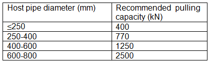
Equipment selection is critical to the success of pipe bursting and splitting. The following Table gives an indication of winch/rod puller capacities necessary for a range of host pipe sizes. Note again that these are winch capacities and are based on tensile force required to pull the bursting/splitting head through the host pipe being burst/split. They are not representative of the tensile load on the PE100 pipe itself which is limited to much lower levels. PE100 pipe manufacturers’ literature provides the maximum allowable tensile loads on pipes.
When upsizing two critical dimensions must be calculated: distance to the surface and distance to existing pipes and structures. First it is necessary to determine the upsize co-efficient.
Upsize co-efficient = OD of expander - ID of host pipe
Where OD of expander is the largest OD of the new pipe PLUS an overcut clearance of between 10 and 30%.
Example: ID of host pipe 150mm; OD of expander 225mm (new pipe OD 200mm + 25mm overcut). Upsize co-efficient is 225 – 150 = 75mm
Depth of cover must be not less than 10 x upsize co-efficient
Distance to existing pipes and structures should be no less than 3 x upsize co-efficient with a minimum of 400mm. in granular soils where the adjacent pipes are brittle and fragile (clay, CI for example) the minimum distance should be no less than 5 x upsize co-efficient with a minimum of 400mm.
If in sporadic lengths the distance to adjacent and crossing pipes is less than these critical distances it is recommended that small excavations be made to observe the passage of the pipe burster/splitter and to monitor any movement.
This method applies tension to the PE100 pipe during installation. The tensile load on the pipe during installation must be calculated to establish whether it exceeds the maximum allowable load. Pipe manufacturers can advise on the allowable loads. If the calculation shows that the maximum permissible load may be exceeded then it may be necessary to increase the capacity of the PE100 pipe by increasing its thickness. This will require a check of ID and OD to ensure that flow capacity and external clearances are still adequate. For pipe bursting and splitting a larger expander may be required which will result in a higher upsize co-efficient.
HEALTH, SAFETY & ENVIRONMENT
All excavations, pits, etc. which personnel will enter must comply with relevant safety regulations covering support and shoring. Relevant confined space entry procedures must also be followed. Examples of relevant legislation are:
- Germany: DIN4124 Excavations & Trenches
- USA: OSHA, State and local regulations
- UK: HSG47, Avoiding Danger from Underground Services; HSG150, Health & Safety in Construction; L101 Safe work in confined spaces.
For safety, reliable communications must be in place between the pipe entry location and the rod puller operator, so the puller can be stopped immediately if anything goes wrong.
Distance to other structures or buried utilities. Refer to above section. PlasticPipe.org
STANDARDS & CODES OF PRACTICE
See Standards and Codes of Practice
COMMON/SECONDARY MODULES
- Pipe assembly & handling
- Installation Manual
- Isolation
- Host pipe cleaning & inspection
- End fittings
- Testing & inspection
- Piecing up
- Pipe bursting and splitting use standard DN and SDR lining pipe so this can be terminated or connected using standard electrofusion or mechanical fittings. It may be necessary, if the pipe to which the new PE100 pipe is being connected has spigot and socket joints which will have little end load resistance, to provide means to absorb the axial tension that will result from internal system pressure variations.
- Excavations & pit sizes
USEFUL LINKS