
Part 4 - Independent Review of NDT of Fusion Welded Joints in PE100 Pipe
It has been established that NDT techniques can be successful in detecting flaws within fusion welded joints, but independent scrutiny is required to establish to what extent the flaws detected are significant in terms of performance of the joints. This can only be established by comparison of results of NDT analysis with destructive mechanical testing currently specified to identify satisfactory performance of the joints. A number of studies have been identified where controlled experiments have been conducted using a variety of NDT techniques and the appropriate specified mechanical test methods:-
-
UK study of EF and BF joints [6]
-
German study of EF joints [3]
-
ISO study of EF joints [10]
-
ISO study of BF joints [11]
UK Study of EF and BF Joints
MWI inspection of both BF and EF welds was conducted in addition to mechanical testing in this study in the UK and reported in 2010 [6].
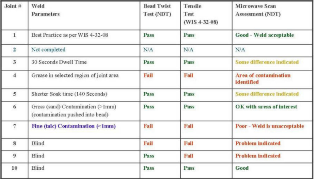
Table 1. Details of the BF welds made and test results obtained
A program of work was carried out to determine the effectiveness and functionality of the MWI technique (from Evisive) in the inspection of PE butt fusion joints. Nine butt fusion welds of PE100 250mm SDR11 pipe were manufactured by a subcontractor, one best practice and eight with varying defects within the weld, three of which were blind samples. The external bead was removed first and a twist test performed on each bead. The samples were then scanned using MWI and the resulting images were assessed to identify any issues with the integrity of the welds. After the scans were performed the welds were marked up for tensile testing. Any areas indicating possible issues with the quality of the weld were marked out and tensile test specimens were taken from these regions as well as other areas around the circumference. The tensile tests were performed in accordance with Appendix B of WIS 4-32-08[1] (equivalent to ISO13953). Table 1 details the welds made and the results obtained.
The following is a selection of the Evisive microwave NDT results obtained. Figure 2 represents the best practice weld which corresponds to a standard scan image of a PE100 butt weld. In assessing butt welds, a good butt weld should have the following characteristics:-
-
A strong unbroken return signal (voltage) from the weld zone
-
Minor return signal variations along the weld
-
Only single line return signal (i.e.- no double line patterns)
-
Regular pattern return from inner bead (if present)
When viewing the images, the X-axis represents the axial distance along the pipe sample, in inches. The Y-axis is circumferential around the pipe also in inches. It represents the full 360° circumference of the weld. Close to the origin a piece of metal tape was attached and is used as a locating point or starting point of the scan. The line running vertically along the scan close to the origin is the manufacturer’s stamp line embedded in the pipe wall. It should be noted that the colour gradients are simply a chosen scale of reference, meaning that the colours can be chosen arbitrarily to aid viewing detail and have no meaning on their own.
FIGURE 1
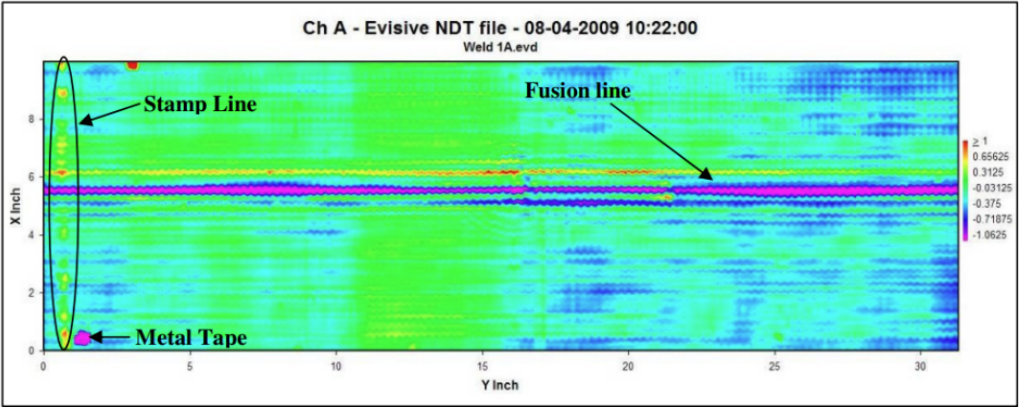
Figure 1. Joint 1 – best practice weld
Three more examples of scans follow of failed joints with the area of issue clearly marked. In total, 4 joints were outright failures according to MWI and this correlated perfectly with failures in the mechanical test. There were also differences observed in two other joints (joints 3 and 5) in the MWI scan obtained, but deemed acceptable, which was confirmed by acceptable mechanical test results. The bead twist also gave good correlation with mechanical test and MWI results, except for joint 9. In the latter case, the bead test passed, but both MWI and tensile test failed, which may have been due to the localised area where the weld failed not being tested in the bead test (bead testing was continuous along the whole length when this testing was completed).
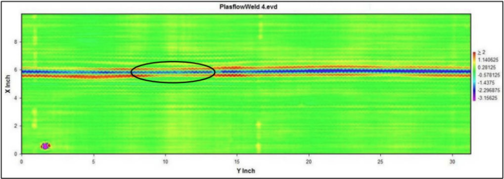
Figure 2. Joint 4 – grease contamination
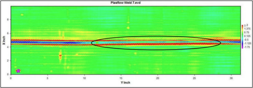
Figure 3. Joint 7 – fine particulate (talc) contamination
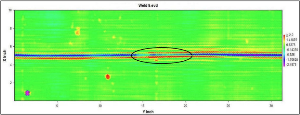
Figure 4. Joint 9 – blind test with defect identified
Further testing of thicker BF joints from the field was also reported, with further indication of good correlation between MWI and mechanical test results.
An evaluation was also conducted of 12 EF couplers that had been in service at various locations in various conditions. These samples were also subjected to MWI inspection and mechanical testing (ISO13954, EN12814-4).
Joint 5 EF (Figure 5) performed well in mechanical testing and also gave good results in MWI.
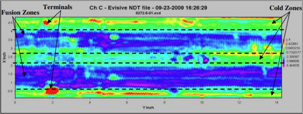
Figure 5. Joint 5 EF showing relatively consistency within the fusion zones
However, Joint 11 EF (Figure 6) gave poor performance in mechanical testing and there was clear evidence from the MWI of melt flowing into the cold zones and much less consistency with the fusion zones overall.
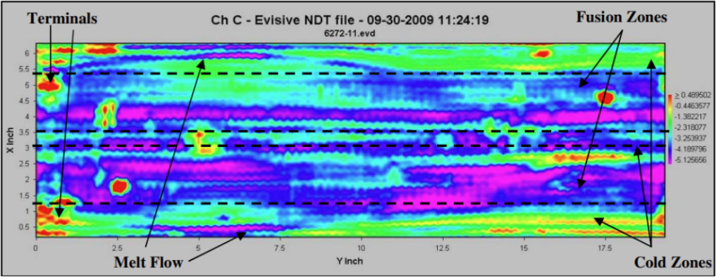
Figure 6. Joint 11 EF showing less consistency within the fusion zones and melt flow into cold zones
A further example (Joint 3 EF, was provided of an EF weld with intermediate performance, with some brittleness in the mechanical testing and significant indications with MWI of inconsistent nature of the signal return in the regions of the fusion zones that does suggest that there is a problem with the quality of the joint.
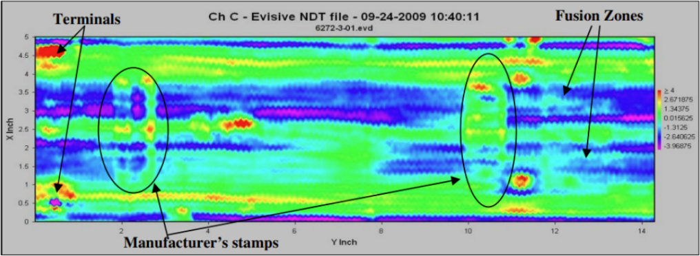
Figure 7. Joint 3 EF showing poor consistency within the fusion zones
Overall, results obtained using MWI for BF welds were relatively easy to interpret and gave good correlation with mechanical testing for a range of defects that were found to result in poor performance. MWI also showed some differences to best practice BF welds for other joints that also passed mechanical testing, suggesting that MWI may be too sensitive. For EF welds, the scans obtained were much more complex and difficult to interpret and it was suggested that it might be beneficial to combine MWI with PAUT to aid interpretation of results.
German Study of EF Joints
In this study, reported by DVGW in 2024 [3], a range of EF couplers from 4 manufacturers were used on 110mm SDR11 pipe. Flaws were introduced into the welds in a controlled manner including: incorrect preparation (scraping), incorrect pipe insertion and contamination with water, oil, sand and leaves. NDT was conducted with Phased Array Ultrasound (PAUT) from 2 sources and Computer Tomography (CT) and mechanical testing conducted in the form of pressure testing (10.8 bar at 80°C for 165 hours) and shear testing (to DVS 2203-6).
Mechanical testing revealed that all samples were able to pass the pressure test, but overall 15% of samples (24/162) failed to meet requirements (two thirds ductility) in the shear test. PAUT was able to detect defects at a rate of 83% (134/162), which was significantly higher than CT at 58% (62/162). Comparison of NDT results with mechanical performance therefore concentrated on PAUT results as follows.
For a summary of results of comparison of PAUT NDT and mechanical performance, four categories were established by the authors, with the following results (with interpretation of the data presented in brackets):-
1. No indication detected & no effect on the mechanical properties: 40% (55/162);
2. Indication detected & influence on the mechanical properties present: 88% (21/162);
3. No indication detected & influence on the mechanical properties present: 13% (3/162);
4. Indication detected & no effect on the mechanical properties: 60% (83/162).
Agreement in 88% of cases between mechanical integrity and PAUT was considered to be a positive result by the authors. From interpretation of the data, this suggests 21/24 samples that failed the shear test were detected by PAUT, but also that 3 of these samples remained undetected by PAUT.
However, the false positive detection of defects (60%) in the NDT test (category 4) is of concern. From interpretation of the data, this suggests 83/162 samples that passed the shear test had indication of defects in the PAUT test.
Overall, the pass/failure criteria appear to be generally set too high in the case of the PAUT results in comparison to shear testing on this occasion, although 3 failures in the shear test were missed by PAUT inspection. If the focus of the PAUT inspection had been detection of defects rather than the criticality of the defect to performance, then this may explain the results obtained, but not for the 3 failures that were missed.
It is observed that this study does not consider fine particulate contamination or inadequate clamping (potential lack of restraint and misalignment of the pipe within the coupler) as defects that are normally highlighted as significant considerations.
ISO International Study of NDT inspection EF Joints using PAUT
An international round robin test (RRT) was initiated by ISO/TC138/SC5/WG17 to investigate Phased Array Ultrasound (PAUT) inspection of EF coupler joints to establish a new test standard for this purpose (ISO/TS 16943) for procedure qualification. The intentions of the round robin consisted of:-
-
Electrofusion couplers from 3 manufacturers, each from different countries;
-
PE100 pipe diameter 160mm SDR11;
-
36 joints made (18 couplers each with 2 fusion zones) in 2 different countries;
-
6 joints made with planar flaws (25 μm thick aluminium discs of 2, 3, 4, and 8 mm in diameter);
-
6 joints made with cold fusion;
-
6 joints made on unscraped pipe;
-
6 joints made with fine particulate contamination;
-
3 joints made with pipe under-inserted;
-
9 joints made without imperfections;
-
PAUT inspection conducted by 7 teams worldwide;
-
For planar flaws: circumferential, axial position noted plus size;
-
Destructive testing performed by 3 teams in 3 different countries;
-
Destructive test used was strip bend test (SBT) to ISO21751 (modified);
-
12 destructive tests from around the circumference were used per each fusion zone, total 432.
-
Electrical terminals and fusion indicators removed to allow unhindered access.
In the event, one of the joints without imperfection was found to be contaminated with fine particulate matter and another failed without explanation. Therefore, 7 joints had fine particulate contamination and the overall number of joints without imperfections was reduced to 7, giving a total of 35 rather than 36. The joints containing unscraped pipe were also excluded from PAUT inspection because it was realised that PAUT could not detect lack of scraping.
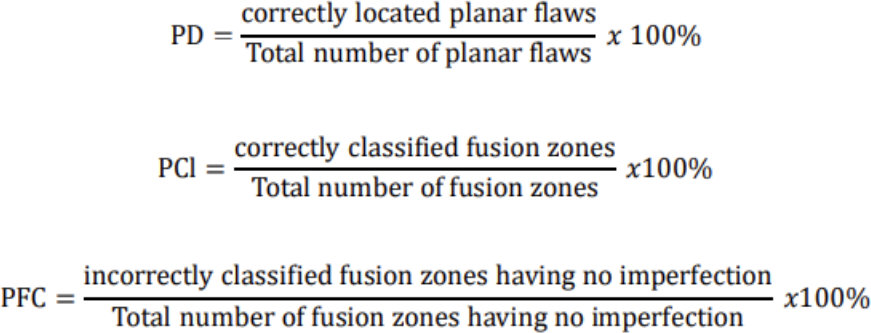
The results were assessed by considering 3 criteria: probability of detection (PD), probability of correct classification (PCI) and probability of false call (PFC) defined as follows:
|
Team |
PD (%) Flaws |
PCl (%) With/without imperfections |
PFC (%) No imperfections |
|---|---|---|---|
|
1 |
100 |
96 |
0 |
|
2 |
71 |
87 |
14 |
|
3 |
96 |
100 |
0 |
|
4 |
92 |
87 |
14 |
|
5 |
46 |
78 |
0 |
|
6 |
100 |
78 |
57 |
|
7 |
96 |
91 |
0 |
|
No. of RRT Specimens |
24 |
22 |
7 |
|
PQ Requirements |
15 of 16 |
18 of 20 |
0 of 8 |
|
ISO/TS 16943 |
≥94 |
≥90 |
0 |
Table 1. Definition of criteria and overall results
It should be noted that PD applies to planar flaws only and this consists of 4 flaws in each of 6 fusion zones, giving a total of 24. PCl applies to joints with/without imperfections other than planar flaws (but not lack of scraping). PFC just applies to joints without imperfections. On the basis of the results obtained, the committee decided that the procedure qualification in ISO/TS 16943 should be:-
-
PD of ≥ 93% (correct detection: 15 of 16);
-
PCl of ≥ 90% (correct classification: 18 of 20);
-
PFC of 0%.
Overall, the RRT was successful in establishing that 100% of defects could be detected (both PD and PCl) by PAUT inspection (providing lack of scraping is excluded, which cannot be detected) with a false call rate of zero (PFC). An alternative test jig for the side bend test of ISO 21571 was also found to be an effective alternative to the current ISO decohesion standard test methods for EF joints.
A second international round robin test (RRT) was initiated by ISO/TC138/SC5/WG17 to investigate NDT methods suitable for inspecting butt fusion joints. In this case, the procedure qualification (PQ) was for ISO/TS 22499 and the NDT methods were extended to:-
-
Phased Array Ultrasound (PAUT);
-
Microwave Imaging (MWI);
-
Time of Flight Diffraction (TOFD);
-
Bead Bendback Test (BBT).
In this RRT the following parameters were intended:-
-
2 pipe materials: PE4710 and PE100
-
3 pipe diameters 6inch SDR9 for PE4710, 225mm and 315mm SDR11;
-
Welding to ISO 21307;
-
4 joints each with 10 planar flaws of 25 μm thick aluminium disks of 1, 1.5, 2, 3 and 6mm diameter;
-
9 joints with cold fusion;
-
9 joints with fine particulate contamination;
-
9 joints with no imperfections;
-
5 different destructive test.
In the event, cold fusion joints were found to be difficult to make in the laboratory, with variable results obtained. Cold fusion joints were therefore excluded from further analysis.
Analysis of the destructive test results indicated that the waisted tensile test (ISO 13953 Type A) was most successful at discriminating between good and bad welds, although the strip bend test (ISO 21751) also showed similar results. The other tests considered were low temperature tensile test (EN12814-6), guided side bend test (ASTM F3183-16) and high speed tensile impact test (ASTM 2634-15). Joints were selected for analysis within the RRT on the basis of results obtained for the waisted tensile test, which resulted in a total of 19 joints being selected. Eight of the joints selected had no imperfections and 11 had imperfections. Tables 1 & 2 contain the overall summary of results with reference to ISO/TS 22499.
Table 1. Range of results obtained for planar flaws using each NDT method
|
|
PAUT |
TOFD |
MWI |
|---|---|---|---|
|
Teams |
5 |
5 |
5 |
|
Detection (%) |
42-93 |
49-86 |
66-72 |
|
Sizing (%) |
160 |
212 |
None |
Table
2. Range of results obtained for imperfections using each NDT method
|
|
PAUT |
TOFD |
MWI |
BBT |
|---|---|---|---|---|
|
Teams |
5 |
5 |
5 |
1 |
|
POD RRT (%) |
18-73 |
55-82 |
82-91 |
82 |
|
POD PQ (%) |
17-83 |
50-83 |
67-83 |
83 |
|
FCR RRT (%) |
25-0 |
50-0 |
63-25 |
0 |
|
FCR PQ (%) |
22-0 |
56-0 |
67-22 |
0 |
Where POD is probability of detection and FCR is false call rate.
It was observed that:
-
One PAUT team achieved PQ requirement on planar flaws
-
One TOFD team and BBT achieved PQ requirement on imperfections
-
MWI (& BBT) was unable to measure planar flaws
-
Planar flaws were generally measured to be larger than they were
Part 1 - NDT of Fusion Welded Joints in PE100 Pipe
Part 1 Non-Destructive Testing of Fusion Joints of PE100 Pipes and Fittings The integrity and performance of PE100 pipelines are significantly influenced by the quality of their joints. The most prevalent methods for joining these pipes are butt fusion joining and electrofusion joining . Butt fusion joining is widely favored for its ability to create strong, continuous connections by heating the pipe ends and pressing them together to form a monolithic joint. Variants in butt fusion...
Part 2 - Phased Array Ultrasonic Inspection of Welded Joints in PE pipes
TWI has been carrying out research and development on non-destructive testing (NDT) using volumetric inspection techniques required for welded joints in PE pipes since the 1980s [12-22], which has culminated in the PolyTest phased array ultrasonic testing (PAUT) system ( www.polytestsystem.com ). The following description is based upon this particular system of PAUT. Conventional ultrasonic inspection uses a single piezoelectric element probe to send ultrasonic waves, typically at frequencies...
Part 3 - Microwave Imaging Inspection of Welded Joints in PE pipes
Microwave Imaging (MWI) inspection is unlike many other NDT techniques in that it is does not have a history of use for metallic materials, for which it is unsuitable, but has been specifically developed for polymeric materials based upon measurement and changes in relative permittivity. It uses a form of electro-magnetic radiation (EMR) in the microwave frequency range between 1GHz and 100GHz (Figure 1). Figure 1. Position of microwaves used for inspection within the range of EMR The use of...
Members of the Association
