
Part 2 - Phased Array Ultrasonic Inspection of Welded Joints in PE pipes
TWI has been carrying out research and development on non-destructive testing (NDT) using volumetric inspection techniques required for welded joints in PE pipes since the 1980s [12-22], which has culminated in the PolyTest phased array ultrasonic testing (PAUT) system (www.polytestsystem.com). The following description is based upon this particular system of PAUT.
Conventional ultrasonic inspection uses a single piezoelectric element probe to send ultrasonic waves, typically at frequencies between 0.1 and 10MHz, into an object and to receive any reflected signal back. The ultrasonic waves travel perpendicular to the probe. PAUT probes, on the other hand, consist of not one, but up to 128 piezoelectric elements, each of which can be pulsed individually with computer-calculated timing to both focus the ultrasonic beam at a particular depth in the object and to steer the ultrasound at different angles without adjusting the position of the probe. This makes it a very powerful tool for detecting defects in welded joints.
Butt fusion and electrofusion joints require very different PAUT inspection procedures due to the location of the imperfections that need to be detected, which will be at the weld interface. For BF joints this is in a plane perpendicular to the outside surface of the pipe, whereas, for EF joints, this is in a plane parallel to the pipe outside surface (Figure 1).
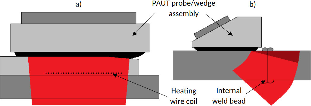
Figure 1
Inspection of PE pipe joints using PAUT:
a) EF joint; b) BF joint
(the red area shows the area of the joint that is inspected).
A two-dimensional ultrasonic image of the inspection area (the red areas shown in Figure 1) is generated by the PAUT system every 1mm or 2mm around the joint circumference, depending on the pipe diameter, in order to generate a three-dimensional dataset of the complete weld, which can then be interrogated using computer software to display cross-sections of the weld in different orientations. As can be seen in Figure 1a, each fusion zone of the EF fitting is scanned separately, so that two 360° scans are required for each joint; only one 360° scan is required for BF joints.
Figure 2 shows a typical display for an EF joint. The sector scan (S-scan) shows a cross-sectional view of the fusion zone in the axial direction at one location around the joint circumference, where the x-axis is the axial direction and the y-axis is the radial direction. The reflected signals from the individual turns of the heating wire coil can clearly be seen as well as the internal and external cold zones and the reflected signal from the inside of the pipe.
The C-scan shows a full 360° plan view of one of the fusion zones in the joint, where the x-axis is the circumferential direction and the y-axis is the axial direction. The image in the S-scan is at the location of the vertical red cursor in the C-scan, so moving this cursor will change the image in the S-scan. The B-scan shows the scan length in cross section, where the x-axis is the circumferential direction and the y-axis is the radial direction. The A-scan shows the raw ultrasonic data at the location of the red vertical cursor in the S-scan.
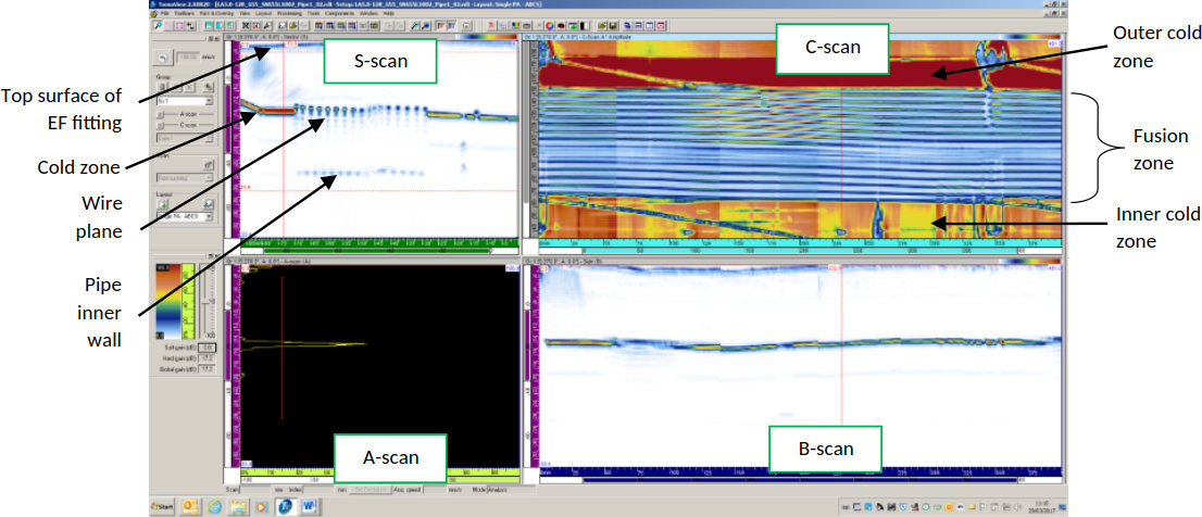
Figure 2 Example of a PAUT display for an EF joint.
Experience has been recorded for use of this system on BF and EF joints in PE (PE80, PE100 and PE4710) pipes and for pipe diameters between 90 and 900mm and wall thicknesses between 8 and 72mm.
The system used consists of the following components (Figure 3):
The PAUT probe: this produces the ultrasonic signal and detects the reflected signals from any imperfection in the joint.
The probe wedge: this ensures that the ultrasound is transmitted from the probe into the PE pipe or fitting at the correct angle and with minimal loss of energy.
The probe carriage and scanning system: this ensures good contact between the probe wedge and the PE pipe/fitting around the whole circumference of the joint without any movement in the axial direction via a system of chain links.
A flaw detector (not shown), which sends electrical signals to the probe, analyses the returning signals and displays the scan output.
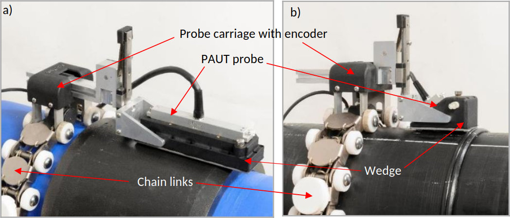
Figure 3 The PolyTest PAUT system for: a) EF joints; b) BF joints.
Phased array probes
PE is a highly attenuating material for ultrasound and the attenuation increases with ultrasonic frequency. This means that, in order to inspect joints in thicker pipes, lower frequencies must be used. Also, lower frequencies are required for inspecting BF joints because, for the same pipe wall thickness, the ultrasound has to travel further due to the beam being angled (see Figure 1). For this reason, four bespoke phased array probes have been designed and manufactured; two for inspecting BF joints and two for inspecting EF joints, each covering a particular pipe/fitting thickness range. As can be seen in Figure 1, the probes for BF and EF inspection are very different; the length of the probes for inspecting EF joints are much longer because they need to inspect the whole fusion zone length.
Probe wedges
A bespoke probe wedge has been designed and manufactured for each of the four PAUT probes. All of the wedges use water as the medium for transmitting the ultrasound from the probe into the PE pipe/fitting. Water is used because it has low ultrasound attenuation and has a velocity ratio that allows the ultrasound beam to be steered towards the BF joint. The water is contained in the wedge using a flexible membrane, which can adapt to the curvature of the pipe and the topography of the EF fitting.
The angle of each BF wedge has been optimised to ensure that the ultrasound covers the whole wall thickness at the joint for the range of pipe sizes for which it has been designed.
Probe carriage and scanning system
The probe carriage is held on the pipe using a series of quick-release wheeled chain links, which can be easily added or removed to accommodate different pipe diameters. The carriage includes a support for holding the probe/wedge assembly, which is spring mounted to ensure that the wedge remains in contact with the pipe/fitting even when it is at the bottom of the joint. The carriage also includes an encoder, which records the circumferential position around the joint.
Flaw detector
PAUT uses a microprocessor-based instrument called a flaw detector to send electronic signals to the probe and receive any returning echoes. They include hardware and software to log, display and analyse the signals. There are many PAUT flaw detectors available commercially.
Laboratory Assessment of the PAUT System
The PAUT system has been assessed in the laboratory and in the field over many years to determine its limits of detection of various flaws (lack of fusion, fine and coarse particulate contamination, oil and grease, cold welds, voids, etc) for different pipe diameters and wall thicknesses. For example, Figure 4 shows PAUT data for a BF joint that contained eight deliberate planar flaws of different sizes, between 1 and 8mm in diameter.
As for the EF joint in Figure 2, the S-scans show a cross-sectional view of the fusion zone in the axial direction at one location around the joint circumference, where the x-axis is the axial direction and the y-axis is the radial direction; the reflected signal from the internal weld bead can clearly be seen in both S-scans. The B-scan shows a full 360° view of the joint, where the x-axis is the circumferential direction and the y-axis is the radial direction. The image in the S-scan is at the location of the vertical red cursor in the B-scan and the image in the B-scan is along the black cursor in the S-scan. Therefore, moving either of these cursors will change the image in the other scans. This needs to be done in order to detect all of the flaws. The A-scan shows the raw ultrasonic data at the location of the cursors in the S- and B-scans.
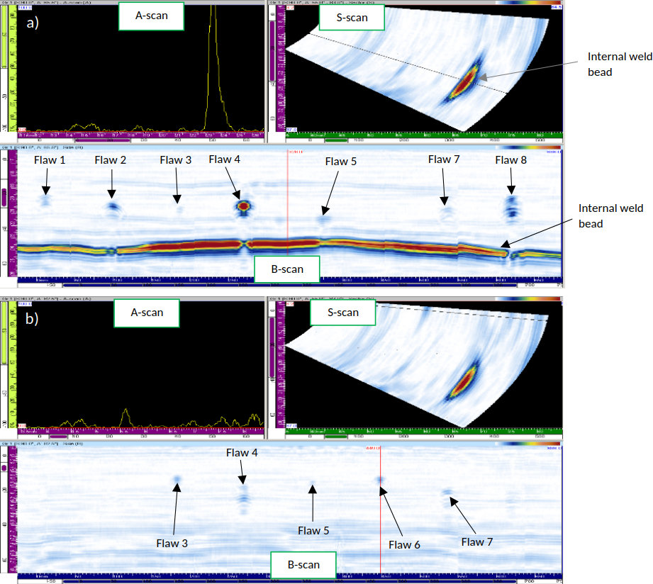
Figure 4a shows the data at a low angle in the S-scan, which means that the reflection from the internal weld bead can clearly be seen in the B-scan image. In addition, seven of the eight flaws can be seen; Flaw 6 was not detected. Figure 4b shows the data at a high angle in the S-scan (i.e. close to the outside surface). In this case the reflection from the internal weld bead cannot be seen in the B-scan. However, Flaw 6 is detected, because it is located towards the outside of the joint. Flaws 1, 2 and 8 cannot be seen in this B-scan image because they are located close to the inside of the joint.
PAUT Case Studies
PAUT Case Study 1 – UK
PE pipe spools that were to be installed in a UK power station were inspected using PAUT in the factory before being delivered on site (Figure 5). The pipes had diameters between 450 and 630mm and wall thicknesses between 36 and 60mm. In total, 88 BF joints were inspected.
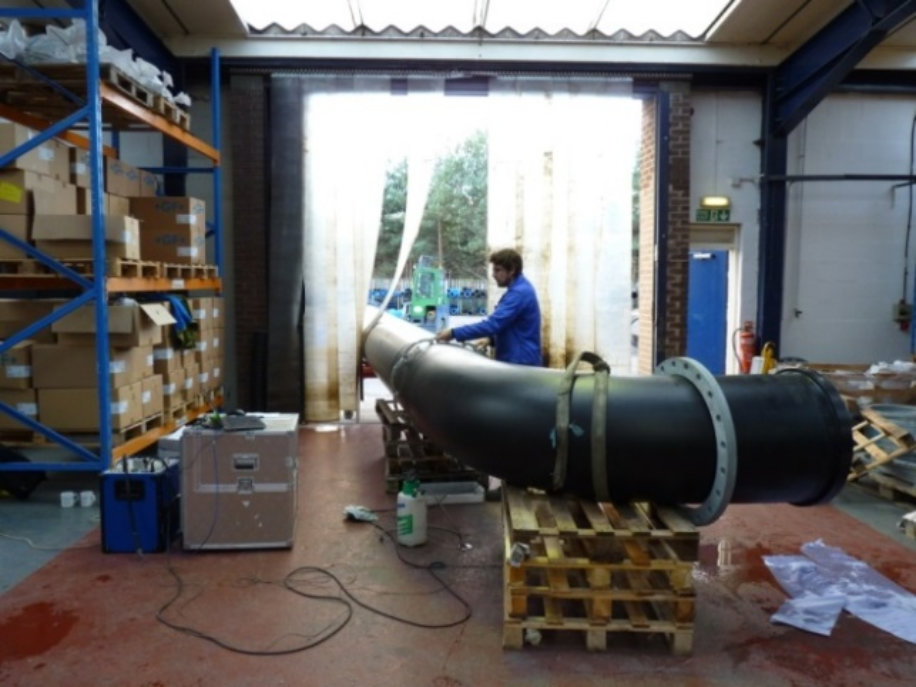
Figure 5 A BF welded 630mm diameter PE pipe spool being inspected using the PolyTest system.
The PAUT scans of all but one of joints revealed no flaws. However, there was an indication in one of the joints, close to the outside surface (Figure 6a). The circumferential position of this indication was marked on the pipe and the joint was subsequently cut out and the section containing the weld was trimmed in a BF machine. The shavings were then analysed for any imperfections at the location of the indication. Figure 6b shows a photograph of the shaving at the location of the indication, revealing a flaw in the joint close to the outside surface.
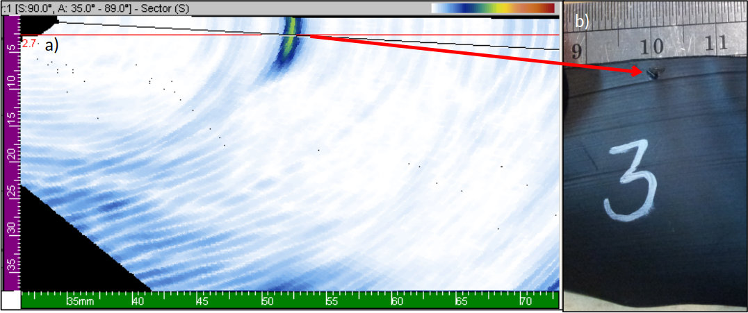
Figure 6 a) S-scan image of one of the BF joints indicating a flaw in the joint; b) photograph of a section through the joint at the location of the ultrasonic indication.
PAUT Case Study 2 – Italy
PAUT inspections were carried out on BF and EF joints in PE gas pipes of diameters between 90 and 315mm in Milan city centre (Figure 7).
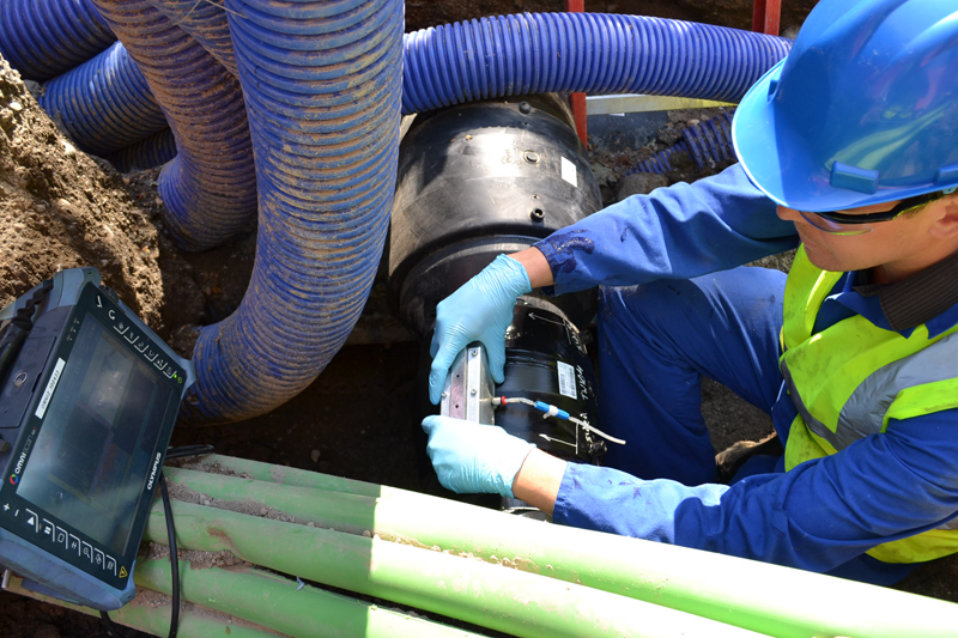
Figure 7 PE gas pipe being inspected in Milan using the PolyTest system.
Although no flaw indications were detected in the majority of the joints, a number were found to contain anomalies. These were cut out and destructively tested, which confirmed flaws that correlated with the PAUT data (Figure 8).
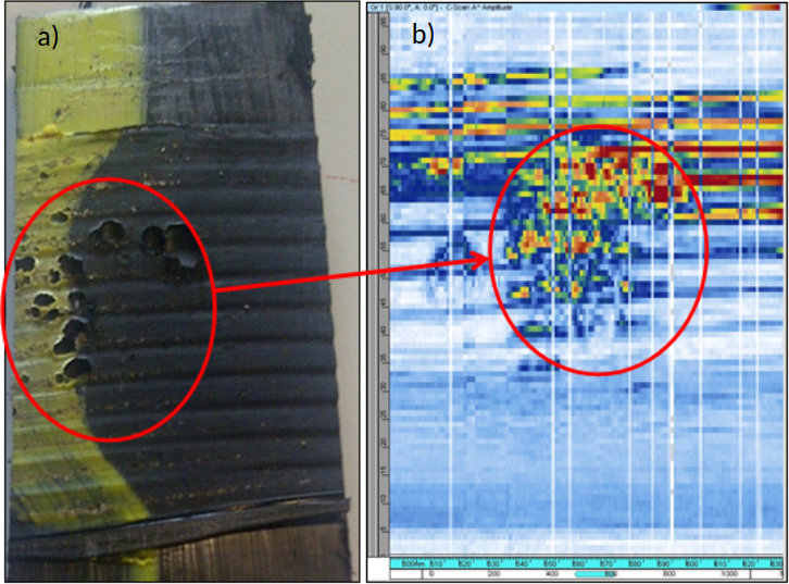
Figure 8 a) Photograph of the fractured interface of a 315mm EF joint, showing voiding at the interface; b) PolyTest C-scan image of the same area before the joint was cut out.
PAUT Case Study 3 – South Pacific
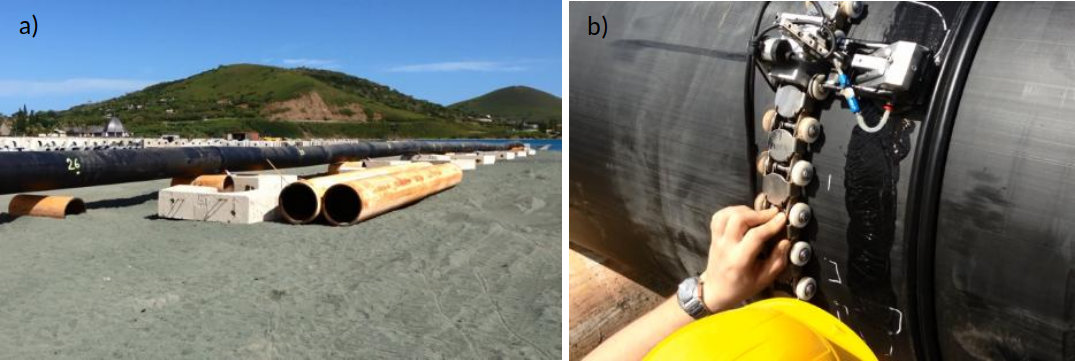
The PAUT system was used to inspect 250 butt fusion joints in an 800mm diameter PE production water marine outfall pipeline for an ore refining company on the island of New Caledonia, located 750 miles off the eastern coast of Australia (Figure 9). The welding and inspection were both carried out on the shore before each pipe string was floated out to sea. None of the welded joints were found to contain flaws, providing assurance of the pipeline’s integrity before it was deployed.
PAUT Summary
On-site inspection of BF and EF joints using PAUT provides a complete analysis of the whole joint that will be employed in service. However, it is important that any NDT system and procedure must be qualified in order to demonstrate that it can detect the critical types of flaw that can occur in these types of welded joint. This is why procedure qualification is a key part of the ISO technical specifications on PAUT of BF and EF joints in PE pipes, ISO/TS 16943 [23] and ISO/TS 22499 [24], respectively. TWI’s PolyTest system conforms to both of these specifications.
In addition, although the PAUT technique can tell you whether there is flaw in the joint, where it is and what size it is, as with any NDT technique, it cannot tell you whether this is a critical flaw (defect) that requires the joint to be cut out. This requires flaw acceptance criteria and TWI has also been active in determining flaw acceptance criteria in BF and EF joints in PE pipes [25-27].
References
Munns IJ and Georgiou G: ‘Ultrasonic and radiographic NDT of butt fusion welds in polyethylene pipe’. Proceedings of the 9th Plastic Pipes conference PPIX, Edinburgh, Scotland, 18-21 September 1995.
Troughton MJ: ‘Welding with integrated non-destructive examination of polyethylene pipes’. Proceedings of the 11th Plastic Pipes conference PPXI, Munich, Germany, 3-6 September 2001.
Caravaca D, Bird C and Kleiner D: ‘The ultrasonic phased array inspection of electrofusion joints in polyethylene pipes’. 45th Annual British Conference on NDT, Stratford-upon-Avon, UK, 11-14 September 2006.
Raude A and Rudlin J: ‘Inspection of in-situ electrofusion welds with a thermal prototype testing device’. 45th Annual British Conference on NDT, Stratford-upon-Avon, UK, 11-14 September 2006.
Bird C, Caravaca D and Raude A: ‘The inspection of cold welds in electrofusion joints’. Proceedings of the 13th Plastic Pipes conference PPXIII, Washington DC, USA, 2-5 October 2006.
Hagglund F, Spicer M and Troughton M: ‘Development and validation of an automated non-destructive evaluation (NDE) approach for testing welded joints in plastic pipes’. Insight, Vol 53(4), April 2011.
Troughton M: ‘Development of ultrasonic inspection techniques and acceptance criteria for butt fusion joints in polyethylene pipes’. Proceedings of the 21st International Conference on Structural Mechanics in Reactor Technology SMiRT 21, New Delhi, India, 6-11 November 2011.
Hagglund F: ‘Development of phased array ultrasonic inspection techniques for testing welded joints in PE pipes’. Proceedings of the 18th World Conference on Non-Destructive Testing WCNDT 2012, Durban, South Africa, 16-20 April 2012.
Hagglund F, Spicer M and Troughton M: ‘ Detection capabilities of a phased array ultrasonic inspection system for plastic pipe butt fusion joints’. BINDT conference, Daventry, UK, 11-13 September 2012.
Hagglund F, Robson M, Troughton MJ, Spicer W and Pinson IR: ‘A novel phased array ultrasonic testing (PAUT) system for on-site inspection of welded joints in plastic pipes’. 11th European conference in Non-destructive testing (ECNDT), Prague, Czech Republic, 6-10 October 2014.
Troughton M and Hagglund F: ‘On-site volumetric inspection of butt fusion and electrofusion joints in polyethylene pipes’. Joining Plastics 10 (2016) 1.
ISO/TS 16943:2023 ‘Thermoplastic pipes for the conveyance of fluids – Inspection of polyethylene electrofusion socket joints using phased array ultrasonic testing’. International Organization for Standardization, Geneva, Switzerland.
ISO/TS 22499:2024 ‘Thermoplastic pipes for the conveyance of fluids – Inspection of polyethylene butt fusion joints using phased array ultrasonic testing’. International Organization for Standardization, Geneva, Switzerland.
Troughton M, Spicer M and Hagglund F: ‘Development of an automated phased array ultrasonic inspection system and flaw acceptance criteria for welded joints in polyethylene pipes’. Proceedings of the 16th Plastic Pipes conference PPXVI, Barcelona, Spain, 24-26 September 2012.
Troughton M and Khamsehnezhad A: ‘Short-term and long-term mechanical testing to evaluate the effect of flaws in butt fusion joints in polyethylene pipes’. Proceedings of the ASME Pressure Vessels & Piping Division Confernce, Vancouver, Canada, 17-21 July 2016.
Troughton M and Khamsehnezhad A: ‘Development of flaw acceptance criteria for welded joints in PE pipes’. Proceedings of the 18th Plastic Pipes conference PPXVIII, Berlin, Germany, 12-14 September 2016.
Part 1 - NDT of Fusion Welded Joints in PE100 Pipe
Part 1 Non-Destructive Testing of Fusion Joints of PE100 Pipes and Fittings The integrity and performance of PE100 pipelines are significantly influenced by the quality of their joints. The most prevalent methods for joining these pipes are butt fusion joining and electrofusion joining . Butt fusion joining is widely favored for its ability to create strong, continuous connections by heating the pipe ends and pressing them together to form a monolithic joint. Variants in butt fusion...
Part 3 - Microwave Imaging Inspection of Welded Joints in PE pipes
Microwave Imaging (MWI) inspection is unlike many other NDT techniques in that it is does not have a history of use for metallic materials, for which it is unsuitable, but has been specifically developed for polymeric materials based upon measurement and changes in relative permittivity. It uses a form of electro-magnetic radiation (EMR) in the microwave frequency range between 1GHz and 100GHz (Figure 1). Figure 1. Position of microwaves used for inspection within the range of EMR The use of...
Part 4 - Independent Review of NDT of Fusion Welded Joints in PE100 Pipe
It has been established that NDT techniques can be successful in detecting flaws within fusion welded joints, but independent scrutiny is required to establish to what extent the flaws detected are significant in terms of performance of the joints. This can only be established by comparison of results of NDT analysis with destructive mechanical testing currently specified to identify satisfactory performance of the joints. A number of studies have been identified where controlled...
Members of the Association
