Introduction
Having established that for some reason a pipe requires rehabilitation, it is important to firstly establish exactly what performance is required. If it is then decided that the necessary rehabilitation, be it renovation or replacement, is to use PE pipe, then a design must be completed to ensure that the chosen pipe will meet the required performance parameters.
The objective of this design module, is to set out and explain all of the things of which the designer needs to be aware and consider, and to present these in a logical and chronological manner so that whilst nothing should be overlooked, a satisfactory design can be offered to the decision module, whilst avoiding unnecessary work.
It is primarily a guide and ‘aide memoire’ not a design programme or procedure, and where equations are included, these are simply examples to make the guide easier to follow.
Setting the design parameters
At the start of the design process, it is necessary to establish the basic operating parameters, namely the capacity or quantity that the pipe will be required to deliver, the hydraulic gradient available to perform the delivery, and the pressure to which the pipe will be subjected in service.
Only two input parameters are necessary in order to use the decision model :
-
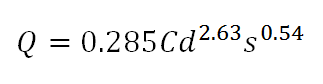
The pipe internal diameter necessary for the flow capacity required. This can be designed using the Hazen-Williams formula below.
-
To know the maximum operating pressure on the pipeline.
It is important that the capacity parameter is sensible and realistic, as there is often an unjustified reluctance to downsize. Certainly, any decision to upsize should be based upon reliable predictions of increased demand, as oversizing can result in stagnation and consequent water quality issues, as well as increased costs. On the other hand, downsizing can result in water shortage and negative system pressure with potential for contamination, under emergency fire demand. This should be carefully considered, even for countries where fire demand supply is not mandatory. Finally, if possible, a degree of latitude should be agreed, as when it comes to the final choice of technique, a considerable saving may sometimes be made if a relatively small reduction in capacity can be accepted.
What size pipe is required?
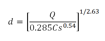
Having decided upon the required capacity and the hydraulic gradient available, the first step in determining the size of pipe required is to calculate the internal diameter. This can be obtained by inputting the capacity Q, friction coefficient C or roughness factor k, and hydraulic gradient s into one of the relevant flow equations, such as Hazen Williams or Colebrooke White, solving for internal diameter d. As PE is extremely smooth, the friction coefficient C for Hazen Williams is generally taken as 150, and the roughness factor k for Colebrooke White 0.03mm.
For example, this is the Hazen Williams flow equation arranged to solve for d:
Because PE pipe is produced using an extrusion process, nominal pipe diameters DN refer to the external diameter, and pipes are manufactured in a series of standard metric sizes, each size generally available in four standard pressure ratings, resulting in four different wall thicknesses. The relationship between the external diameter and the wall thickness is known as the Standard Dimension Ratio or SDR and is simply the ratio of external diameter to wall thickness. These four are SDR11 which is rated at 16bar, SDR17 rated at 10bar, SDR26 rated at 6bar, and SDR33 rated at 4bar, though SDR33 should only be used as an interactive lining pipe, and not as an independent pipe.
Having decided upon the pressure to which the pipe will be subjected, the appropriate SDR can be selected, and the second step in determining the size of pipe required is to choose the nominal pipe size DN that has an internal diameter closest to, but not smaller than, the internal diameter d determined in step one. This pipe will be a nominal standard size DN and SDR, with the benefits of being readily available as a stock item, at least in the small to medium ranges, as well as having a standard range of fittings available, this latter having substantial cost saving implications.
In fact, more than four SDRs may be available from some manufacturers, such as ‘in between’ SDR13.6 and SDR21 so it is always worth checking.
The range of standard SDRs is calculated using a service coefficient C, not to be confused with the friction coefficient C used in the Hazen Williams flow equation. The default value for water is 1.25 and this is simply a safety factor to accommodate any site or operational factors that might effect the performance of the pipe or shorten it’s life. If there are any other relevant factors such as temperature, the chemistry of the fluid to be carried or the surrounding ground, then the value of C can be increased accordingly, and the appropriate SDR calculated using the equation:
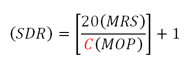
where (MRS) is the minimum required strength of the lining pipe material in MPa, and (MOP) is the maximum operating pressure in bar.
The UK IGN 4-32-18 gives guidance on temperature related de-rating, and particular care should be taken when lining pipes operating above ground in climates with large temperature variations, due to the large difference in the coefficient of thermal expansion between PE and metallic host pipe materials.
Will it be possible to line the existing main?
It may be possible to satisfy the required parameters by simply inserting a nominal standard DN and SDR pipe inside the existing main. If not, it may still be possible to satisfy the required parameters by close fit lining the existing main, and here any latitude agreed on the required capacity when initially setting the design parameters could have substantial cost saving implications.
For any lining technique other than slip lining, it is necessary to reliably establish the condition, internal diameter, and residual strength of the existing main, and this can be done without taking the main out of service by using under pressure tapping to remove coupons for metallurgical testing and inserting CCTV equipment, and carrying out external ultrasonic scanning of the main at various locations along it’s length. These procedures are covered in detail in the lining technique modules.
In the case of close fit lining, the external diameter of the lining pipe is fixed by the internal diameter of the main to be lined, and the appropriate SDR is then applied to find the internal diameter of the lining pipe, from which the available capacity can be obtained from one of the flow equations used in the first step, now solving for quantity Q.
Such a pipe of non standard DN and SDR will potentially cost more, as the manufacturer has to reconfigure the extrusion line, and non standard fittings will be required, however, if for instance the maximum operating pressure is only around 12bar, then the selection of an SDR of 13 rather than 11 would use less PE, and on a large diameter and long pipeline, could result in large savings.
What about an interactive lining?
If it is not possible to satisfy the required parameters using a close fit independent lining, and if the existing main is structurally sound, then it may still be possible to satisfy the required parameters by inserting an interactive lining. In such a case, the lining pipe is simply required to span perforation leaks and gappy joints, and it may be possible to use an SDR of 40 or even 50 depending upon the size of the leaks and gaps to be spanned. Also, as an interactive liner will require substantially less PE and maximizes the hydraulic capacity, it is always worth considering, even if the required parameters can be satisfied using an independent lining.
Completely dislocated joints or circumferentially cracked pipes must not be treated as gaps when considering an interactive lining pipe, and in such cases an independent lining pipe is essential.
Research has shown that for a void or gap of 60mm, and this is larger than any gaps so far found in the UK on rehabilitation works, a liner wall thickness of just 6mm will support 16bar for at least a fifty year life, and this is SDR 50 on a 300mm pipe, implying that even larger SDRs could be employed on larger diameter mains. However, there will be times when a main is out of service and empty, and at such times the liner may be subjected to a net positive external pressure due to ground water, and the liner must have sufficient ring stiffness to avoid collapse. This may well require a smaller SDR than that necessary to just span voids and gaps.
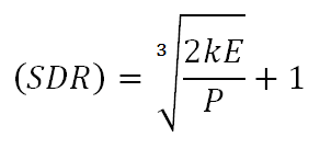
Lining pipe collapse in such circumstances will be by buckling, and in the case of a close fitting lining pipe, resistance to unrestrained buckling is enhanced by the degree of tightness of the fit by a factor k which has a value of 7 for a perfect fit, but generally less than this for the sort of fit expected in practice. The critical SDR at which buckling may occur can be calculated by inputting the flexural modulus E and the potential maximum external pressure P plus an appropriate safety factor, into a ring stiffness equation:
For example, here arranged to solve for (SDR)
It is very important that in determining the potential maximum external pressure that can be exerted during ‘empty main’ situations, the topography along the route is examined. In hilly terrain, water may enter the host pipe/lining pipe interface annulus at a high point, thus subjecting the lining pipe at a relatively low point to a head in excess of the actual water table at that low point. Even in service, the lining pipe may experience net positive external pressure during surge conditions, and in deciding whether to use short term or long term flexural modulus in the design, it should be remembered that negative surge pressure pulses can be measured in minutes rather than seconds when dealing with long mains of large diameters, whilst ‘empty main’ situations can last for months rather than hours.
External load resistance
In the case of all the lining techniques, and for that matter for auger boring too, the lining pipe is shielded by the host pipe from any external loads other than the effect of ground water, so that neither soil loading nor live loading apply.
For the remainder of the trenchless techniques, unlike the conditions where a pipe is newly laid by open cut, and is subjected to substantial forces both during and after reinstatement, the PE pipe is installed into ground that has been in equilibrium for many years. As the ground around the small annular space created during installation relaxes and comes into contact with the pipe, the pipe will only be subjected to a small symmetrically applied radial force. It is however always prudent to check that no particular site conditions exist that might alter this, and if so, to use one of the design procedures for flexible pipe, and if necessary select a lower SDR to provide sufficient ring stiffness to prevent failure if asymmetric loading is considered to be possible and significant.
Flexible pipe design procedures must always be applied if piecing up with PE, as these are inevitably open cut, and similar consideration should be given to pipes in infrastructure congested locations, where third party excavations are likely to create open cut conditions.
PE100 Pipe - Properties and Types
Follow this link to "Properties and Types" section
Decision Module
To evaluate your projects suitability for a trenchless PE100 pipe installation, please follow the link bellow.
Members of the Association
Top articles
PE100+ position letter on ANPT
(SCG) resistance on pipes for pressure applications since many years. With the introduction of PE 100-RC materials in EN 1555, EN 12201 and ISO...
PE 100-RC+ Quality Materials List
PE 100-RC+ materials have become an essential and well established sub-family of PE 100 compounds. They have a higher stress crack resistance and...
PE 100+ association leads permeation tests for H2 ready certification
A number of gas utilities and grid owners have approached the PE 100+ association regarding the suitability of PE 100 pipe systems for the...
Why choose PE compounds for pressure pipe ?
Simplicity or consistency The simplest way for any polymer producer to operate is to produce natural pellets for a wide range of applications...
PE100+ Quality Materials List
PE100+ Quality Materials List is valid until December 2024. It is available online and a PDF version can be downloaded at the bottom of this page.
What range of pipe diameters is available?
PE100 can be manufactured in a wide range of polyethylene pipe diameters from 16mm to 2000mm. Even larger diameters are possible with the development...
What is SDR pipe and how does it influence the pressure rating of the pipe?
SDR pipe : "Standard Dimensional Ratio" The SDR pipe is the "Standard Dimensional Ratio" and refers to the geometry of the pipe. SDR is defined as...
Standard test methods
Creep rupture strength - Internal pressure test Constant internal pressure at constant temperature The internal pressure test is standardised in ISO...
Pipe Bursting and Splitting
PIPE BURSTING / SPLITTING - TECHNIQUE Pipe bursting and pipe splitting are trenchless methods used to replace existing pipelines with PE100 in the...